OK, here you go. Those of you who do those super neat and tidy stereo installs that I've been looking at in other threads are gonna laugh at my crude workmanship, though.


The red things that look like Lego bricks are rubber covers over Bussman ShortStop circuit breakers. (And yes, a couple of those relay wires are a bit tight. After seeing the photos I went in and re-dressed them with more slack. Funny how these things don't show up until you look from just the right angle.)
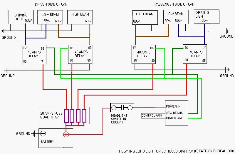
And here's the wiring diagram -- click for a larger, hopefully legible version. I apologize for the hand-drawn diagram but it was originally just for my own reference.

Wire colors marked with a * on the diagram are the color codes in the existing harness.
A few notes:
- It would have been far more efficient from a wiring standpoint to mount one relay on each side of the car, putting the relays near their respective lights. The only reason I didn't do it that way is there isn't a lot of room to mount anything on the driver's side of the engine bay. I was having a hard time finding a spot to mount a relay over there that wouldn't get in the way when I needed to change the air filter, fuel filter, or battery, and goodness knows there's enough in the way already.
It ended up being easier to just mount both relays together and add a couple more wires to the bundle I already had crossing the front of the car.
- I'm running stock bulbs. For higher wattage lamps you'd want to uprate the circuit breakers, relays, and wire sizes accordingly.
- The 10 ga. red and black wires near the top of the photo are for an unrelated 2-way radio install, although I did tap into the black one for ground, since it was already headed over to the battery post.